Calculation of a Motor’s Max. Torque
Maximum torque is calculated by motor’s rotational speed(rpm), output power and reduction ratio etc. The safety factor (in the below table) has to be considered by all means in case motor’s torque information is not available.
- Tmax = Max. Motor Torque [Nㆍm]
- Pmax = Max. Output Power [kW]
- N = Rotational Speed [rpm]
- i = Gear Reduction Ratio
- SF = Safety Factor
| Load Conditions | Safety Factor (SF) | |
|---|---|---|
| Low Inertia | At 60% (or less) of motor’s rated torque | 1.5~2.0 |
| Medium Inertia | Longer acceleration/deceleration time, limited reverse motion and small impact | 2.0~3.0 |
| High Inertia | Shorter acceleration/deceleration time, frequent reverse motion and large impact | 3.0~5.0 |
Tmax (Max. Motor Torque) < Tc (Max. Permissible Torque of A.P. Lock)
Max. motor torque (with SF applied) must be lower than max. permissible torque of A.P. Lock.
Thrust Load
P (Max. Thrust Load) < Pt (Max. Permissible Thrust Load of A.P. Lock)
The thrust load on A.P. Lock’s fastening area must be lower than max. permissible thrust load of A.P. Lock.
Combined Torque and Thrust Load
If torque and thrust load occur simultaneously, please refer to the below formula for load calculation.
- Tcomb = Combined Load [Nㆍm]
- Pmax = Max. Motor Output Power [KW]
- N = Rotational Speed [rpm]
- d = Shaft Diameter[mm]
- P = Thrust Load[N]
- SF = Safety Factor
Tcomb (Combined Load) < Tc (Max. Permissible Torque of A.P. Lock)
Combined Load of torque and thrust must be lower than max. permissible torque of A.P. Lock.
Permissible Torque Variation
- Permissible Torque Increase
When several A.P. Locks are used together, permissible torque and thrust load gets increased.
※ Make sure all foreign substances must be removed from surface of the both shaft and inner part of A.P. Lock. - Permissible Torque Decrease
When the shaft has an additional keyway, permissible torque would be decreased by appx. 20% due to reduced contact area.
Shaft Design Guide
- Please refer to each overview pages for shaft tolerance.
- Check the strength of shaft’s raw material.
- σs : Yield stress of shaft’s raw material [Mpa]
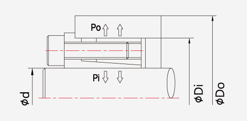
- Pi : Surface pressure onto shaft by A.P. Lock [Mpa]
- Determine max. inner diameter of hollow shaft.
High surface pressure is delivered on the shaft. Thus, make sure the below formula is referred when the hollow shaft is designed.- di : Inner dia. of hollow shaft
- d : Outer dia. of hollow shaft
- σs : Yield stress of shaft’s raw material [Mpa]
- Pi : Surface Pressure onto Shaft by A.P. Lock [Mpa]
Hub Design Guide
- Please refer to each overview pages for hub tolerance.
- Check the strength of hub’s raw material.
- σh : Yield stress of hub’s raw material [Mpa]
- Po : Surface pressure onto hub by A.P. Lock [Mpa]
-
Check the min. hub outer diameter.
You may refer to the below formula in case the material information is not available.- Do : Outer dia. of hub [mm]
- Di : Inner dia. of hub [mm]
- σh : Yield stress of hub’s raw material [Mpa]
- Po : Surface pressure onto hub by A.P. Lock [Mpa]