

Dimensions / Performance
TIMING PULLEY (Unit:mm)
|
TYPE |
CAD |
NT |
P.C.D. |
O.D. |
C |
B |
ID Range (I type) |
ID Range (O type) |
|
|
BW150 (A:16.3, W:20) |
BW120 (A:13.3, W:17) |
BW150 (A:16.3, W:20) |
|||||||
|
SATP-5GT SPAS
|
24 |
38.20 |
37.06 |
42 |
30 |
8 |
8 |
8 |
|
|
25 |
39.79 |
38.65 |
43 |
32 |
8 |
8 |
8 |
||
|
26 |
41.38 |
40.24 |
45 |
33 |
8, 10 |
8, 10 |
8, 10 |
||
|
28 |
44.56 |
43.42 |
48 |
36 |
8, 10 |
8, 10 |
8, 10 |
||
|
30 |
47.75 |
46.61 |
51 |
39 |
10 |
10 |
10 |
||
|
32 |
50.93 |
49.79 |
55 |
42 |
10 |
10 ~ 14 |
10 ~ 14 |
||
|
34 |
54.11 |
52.97 |
58 |
46 |
10 |
10 ~ 14 |
10 ~ 16 |
||
|
36 |
57.30 |
56.16 |
61 |
49 |
10 |
10 ~ 14 |
10 ~ 16 |
||
|
40 |
63.66 |
62.52 |
67 |
55 |
10 |
10 ~ 14 |
10 ~ 19 |
||
|
44 |
70.03 |
68.89 |
74 |
62 |
- |
12 ~ 14 |
12 ~ 19 |
||
|
48 |
76.39 |
75.25 |
80 |
68 |
- |
12 ~ 14 |
12 ~ 19 |
||
|
50 |
79.58 |
78.44 |
83 |
71 |
- |
12 ~ 14 |
12 ~ 19 |
||
|
60 |
95.49 |
94.35 |
99 |
87 |
- |
12 ~ 14 |
12 ~ 19 |
||
* Please refer to the below table for more specific available ID(d) information.
A.P. LOCK(Unit:mm)
|
Available ID (d) |
8 |
10 |
12 |
14 |
15 |
16 |
17 |
18 |
19 |
|
|
Max. Permissible Torque (N·m) |
I & O type |
22 |
25 |
50 |
65 |
70 |
75 |
110 |
115 |
120 |
|
Max. Permissible Thrust Load (kN) |
I & O type |
5.6 |
5.6 |
5.6 |
9.5 |
9.5 |
9.5 |
12.6 |
12.6 |
12.6 |
|
D |
I & O type |
23.5 |
25.5 |
28.5 |
30.5 |
31.5 |
33 |
33.5 |
34.5 |
35.5 |
|
N |
I & O type |
6 |
6 |
6.5 |
6.5 |
6.5 |
6.5 |
6.5 |
6.5 |
6.5 |
• Keyway is NOT available for SPAS series.
• Surface treatment may not be applied on inner surface of Pulley’s body.
How to Order
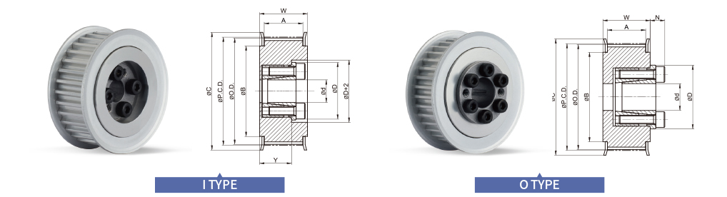
① Shape
- I
- Flange part of A.P.Lock and Taper bushing is located inside
- O
- Flange part of A.P.Lock and Taper bushing is located outside
② Surface Treatment
- HA
- Hard Anodizing
- WA
- White Anodizing