

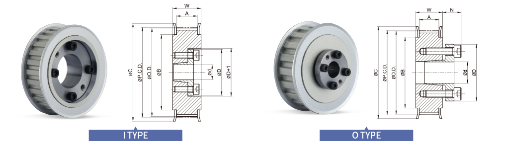
Dimensions / Performance
TIMING PULLEY (Unit:mm)
|
TYPE |
CAD |
NT |
P.C.D. |
O.D. |
C |
B |
ID Range (I type) |
ID Range (O type) |
||||
|
BW150 (A:16.7, W:23) |
BW200 (A:21.7, W:28) |
BW250 (A:26.7, W:33) |
BW150 (A:16.7, W:23) |
BW200 (A:21.7, W:28) |
BW250 (A:26.7, W:33) |
|||||||
|
SATP-8YU SPB |
20 |
50.93 |
49.56 |
62 |
40 |
12 |
12 |
12 ~ 15 |
12 ~ 17 |
12 ~ 17 |
12 ~ 17 |
|
|
22 |
56.02 |
54.65 |
64 |
45 |
12 |
12 ~ 17 |
12 ~ 17 |
12 ~ 17 |
12 ~ 17 |
12 ~ 17 |
||
|
24 |
61.12 |
59.75 |
70 |
50 |
12 |
12 ~ 17 |
12 ~ 17 |
12 ~ 17 |
12 ~ 17 |
12 ~ 17 |
||
|
25 |
63.66 |
62.29 |
72 |
52 |
12 |
12 ~ 22 |
12 ~ 20 |
12 ~ 20 |
12 ~ 20 |
12 ~ 20 |
||
|
26 |
66.21 |
64.84 |
75 |
54 |
- |
14 ~ 22 |
14 ~ 20 |
14 ~ 24 |
14 ~ 24 |
14 ~ 24 |
||
|
28 |
71.30 |
69.93 |
80 |
59 |
- |
16 ~ 28 |
14 ~ 25 |
14 ~ 25 |
14 ~ 25 |
14 ~ 25 |
||
|
30 |
76.39 |
75.02 |
85 |
64 |
- |
16 ~ 32 |
14 ~ 32 |
14 ~ 32 |
14 ~ 32 |
14 ~ 32 |
||
|
32 |
81.49 |
80.12 |
90 |
69 |
- |
20 ~ 35 |
14 ~ 32 |
14 ~ 32 |
14 ~ 32 |
14 ~ 32 |
||
|
34 |
86.58 |
85.21 |
95 |
74 |
- |
20 ~ 35 |
16 ~ 35 |
16 ~ 35 |
16 ~ 35 |
16 ~ 35 |
||
|
36 |
91.67 |
90.30 |
100 |
79 |
- |
20 ~ 35 |
16 ~ 35 |
16 ~ 35 |
16 ~ 35 |
16 ~ 35 |
||
|
38 |
96.77 |
95.40 |
105 |
84 |
- |
20 ~ 35 |
20 ~ 35 |
16 ~ 35 |
16 ~ 35 |
16 ~ 35 |
||
|
40 |
101.86 |
100.49 |
110 |
89 |
- |
20 ~ 35 |
20 ~ 35 |
20 ~ 35 |
20 ~ 35 |
20 ~ 35 |
||
|
44 |
112.05 |
110.68 |
121 |
99 |
- |
20 ~ 35 |
20 ~ 35 |
20 ~ 35 |
20 ~ 35 |
20 ~ 35 |
||
|
48 |
122.23 |
120.86 |
131 |
109 |
- |
20 ~ 35 |
20 ~ 35 |
20 ~ 35 |
20 ~ 35 |
20 ~ 35 |
||
|
50 |
127.32 |
125.95 |
136 |
114 |
- |
20 ~ 35 |
20 ~ 35 |
20 ~ 35 |
20 ~ 35 |
20 ~ 35 |
||
|
60 |
152.79 |
151.42 |
161 |
140 |
- |
20 ~ 35 |
20 ~ 35 |
20 ~ 35 |
20 ~ 35 |
20 ~ 35 |
||
* Please refer to the below table for more specific available ID(d) information.
• Due to structural reasons, the following I type ID ranges (from 12 to 30 (BW250)) use O type taper bushings as an exception.
TAPER BUSHING(Unit:mm)
|
Available ID (d) |
12 |
14 |
15 |
16 |
17 |
18 |
19 |
20 |
22 |
24 |
25 |
28 |
30 |
32 |
35 |
|
|
Max. Permissible Torque (N·m) |
I type |
23 |
37 |
39 |
42 |
45 |
48 |
49 |
97 |
110 |
121 |
124 |
141 |
149 |
163 |
173 |
|
O type |
48 |
73 |
78 |
83 |
88 |
154 |
163 |
171 |
186 |
206 |
216 |
353 |
382 |
412 |
451 |
|
|
Max. Permissible Thrust Load (kN) (kN) |
I type |
3.76 |
5.21 |
5.1 |
5.17 |
5.23 |
5.28 |
5.12 |
9.68 |
9.98 |
10 |
9.9 |
10 |
9.89 |
10.12 |
9.88 |
|
O type |
5.34 |
5.34 |
5.34 |
5.34 |
5.34 |
8.74 |
8.74 |
8.74 |
8.74 |
8.74 |
8.74 |
8.74 |
8.74 |
8.74 |
8.74 |
|
|
D |
I type |
31 |
36 |
37 |
38 |
39 |
40 |
42 |
46 |
47 |
49 |
51 |
53 |
56 |
58 |
61 |
|
O type |
32 |
35 |
36 |
37 |
38 |
43 |
45 |
46 |
48 |
50 |
52 |
54 |
57 |
59 |
63 |
|
|
N |
O type |
10.5 |
12 |
12 |
13 |
13 |
14 |
14 |
14 |
14 |
14 |
14 |
15.5 |
15.5 |
16.5 |
16.5 |
• Keyway is NOT available for SPB series.
• Surface treatment may not be applied on inner surface of Pulley’s body.
How to Order
① Shape
- I
- Flange part of A.P.Lock and Taper bushing is located inside
- O
- Flange part of A.P.Lock and Taper bushing is located outside
② Surface Treatment
- HA
- Hard Anodizing
- WA
- White Anodizing